This project's purpose was to duplicate the function of the early (1939 to 1953) Ford V8 temperature indicator operation. As the two banks of the V8 were isolated, the gauge used a temperature sender in one bank and an over temperature limit switch in the other bank; wired in series. Thus if the bank with the limit switch over heated the circuit would open and the gauge would go to full scale hot. This system was a King Seely design. When using the more common resistive sending units and after market gauges this function is lost and this project attempts to replace it. I added a switch and LED's to select which sender is connected to the gauge; the other sender is monitored by a circuit that flashes a red LED if that side overheats. The picture on the left shows the left sender selected; the other picture shows what happens when the monitored side overheats. Note that the engine is not running in these pictures, I forced the right side to show an overheat situation.
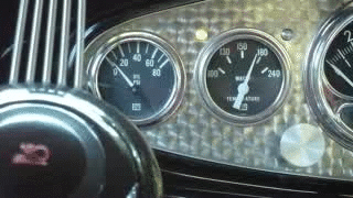
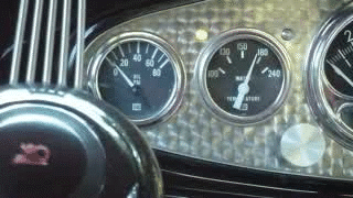
Separate temperature senders are used in each bank and the sender connected to the gauge is selected by a relay which is operated by a toggle switch. Red/Green dual color LED's are mounted on either side of the gauge to indicate which sender is being monitored by the gauge, with the green LED indicating the side selected; which in the picture is the left side. The right engine bank sender is the input to a comparator and if the temperature rises to the set point the comparator switches and enables an oscillator which flashes the red LED on the right side of the meter to indicate a fault.
To see the schematic of the circuit click here:
Dual Temp Monitor SchematicHere is a description of how the circuit operates:
K1 is a dual pole relay controlled by a toggle switch that selects which side of the engine that is being read by the gauge and connects the other side to the over temperature monitoring circuit. The left side is connected to the gauge in the schematic and the right side is monitored by the circuit. I am using a Stewart Warner gauge and senders which vary from 240 to 33 ohms over the normal engine temperature range, with 33 ohms at the the hot end of the scale. The right side sender is connected in series with a 250 ohm resistor and the negative input to IC1B, a comparator that will switch to a high (12 volt) state when the voltage at the negative input falls below the set point of the positive input; as controlled by the setting of the 1K pot. The high output of the comparator will now enable the oscillator IC1D. The pulses from the oscillator will now flash the red section of the right LED.
The operation of the left and right LED's is as follows: The toggle switch is in the Left position and the inputs to NOR gate IC2C are pulled high, causing the output to be low. Normally the oscillator is disabled and its output is low. IC1C inverts that low voltage and puts a high signal to pin 1 of NOR gate IC2A. The output of IC2A is thus low. With low signals at both ends of the right LED, there is no current flow through either of the LED sections. If the oscillator is enabled by a high temperature the input to pin 1 will alternate high and low. During the low period the output will go high and the red LED section of the right LED will turn on.
The output of IC2D is high and is connected to the bottom of the left LED and to an input of IC2B which makes the output of IC2B low no matter what the other input is. Thus the green section of the left LED is always on when the toggle switch is in the Left position. When the toggle switch is placed in the Right position the action of the gates reverses. The CMOS gates with their FET outputs can sink or source current and so just two wires are needed to each LED.
The trip point of the comparator is calibrated by substituting a variable resistance in place of one of the sensors. The toggle switch can be used to read the temperature on the gauge to select the temperature point desired and then switched back to connect the test resistance to the monitor circuit and the trip point is then set by the 1K pot. The Stewart Warner gauge in my car has a 240 to 33 ohm sender; the gauge reads 180 at 61 ohms and 240 at 28 ohms. I set my trip point at around 50 ohms which corresponds to 210 degrees.
As there was one amplifier left of IC1 I decided to use it to provide a regulated 10 volt source to power the inputs to the comparator.
Created on ... May 10, 2015